Homebrew
Radio Projects - Ted Crosby's HBR-12 Dual Conversion Super
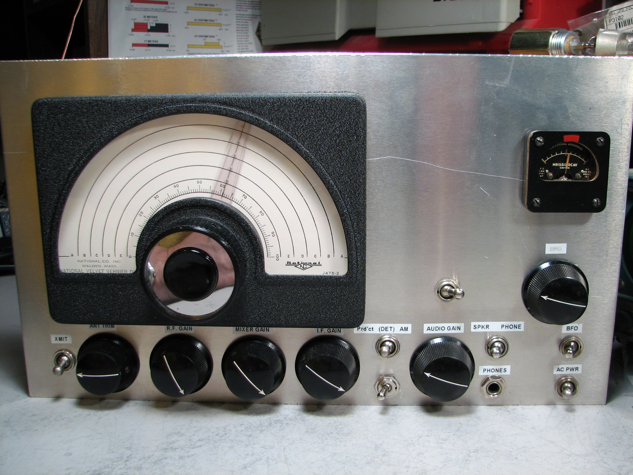
HBR-12
Front View
Top View
Top Opened
Raw Front Panel
Chassis Before Front
Ground Post Wiring
Ground Post Wiring
Technique
Chassis layout
Masking tape protection
Chassis punched
Well, this project is certainly the apex of my homebrew radio receivers!
When I saw the HBR receiver feature article that ran in QST magazine, I
knew right away that I'd need to build one of these fascinating receivers.
Like most of my radio projects, there is some special feature that drove
me to experience it first hand. In this case, it was the double-conversion
system and the product detector, neither of which I had ever experienced
before.
Of course, the plethora of these radios that can be located on-line is
exciting as well. And, this has to be one of the most thoroughly
documented projects, both from a construction/operational standpoint as
well as the fascinating history of the design evolution.
My first challenge was to locate parts (as is always the case).
Unfortunately, I did not locate the "exact" tuning capacitor until well
after I had completed the construction of this project.
And, I'm still experimenting on how to create my own "polystyrene" coil
forms. This project started with the fabrication of my own chassis
out of 0.090" aluminum.
The front panel construction is my favorite method of employing 0.090"
black anodized aluminum that is laser engraved. I laid out the artwork
using CorelDraw on a PC.
It was a real challenge to cram all the required components into such a
small footprint! I'm not sure that I could take it apart again if I ever
need to make repairs :-)
Note the "special" technique that was used to cram the components into a
restricted space: A one-inch length of 12-gauge tinned-copper wire was
soldered to the base of each tube socket. This vertical length of wire is
utilized as the
local "ground" connection for all neighboring components.
Not only does this serve to facilitate short ground leads, but also it
allows for the positioning of the components in a vertical (rather than
horizontal) position.
I did wind the first-stage coupling-coils with my Gingery Coil Winder.
And, I used the 262 KHz K-Tran type I.F. cans which I had to modify to the proper
I.F. frequency and coupling. Unfortunately, I melted the polystyrene
in my first attempt. Then I discovered that a better technique is to
disassemble the coil and apply heat with a solder pencil. Luckily I
was able to repair the I.F. coil by using parts from discarded coil parts
that I found at a swap-fest.
I was lucky enough to find an old metal cabinet (that I repainted with
crinkle finish paint)
and a National ACN dial. I wish I could have located an appropriate
Eddystone, but .. Oh well :-)